
Three-Phase Induction Motors Energy Efficiency Standards – A Case Study –
- abhishek1486
- Dec 18, 2024
- 8 min read
Abstract. The efforts to reduce the energy consumption begin with its main load, the induction motor. There is a world agreement that this objective can be achieved by motors efficiency regulation. The Brazilian Government has already approved regulations establishing mandatory limits for Standards and High Efficiency Motors. This paper analyzes the results achieved so far through tests realized at LAMO-TRIZ/DEE-UFC with both types of motors and points to the challenges that the domestic industry will have to overcome to improve even more these machines efficiency.
Keywords
efficiency, induction motors, losses, regulation, premium.
1. Introduction
Currently, the voluntary or mandatory regulation of machines and equipment efficiency levels has become a tendency in different countries around the world. This process began in the 70s and evolved to a complex system of energy performance labeling and standardization. In order to harmonize these different initiatives related to motors, there is an oficial initiative (SEEEM - Standards for Energy Efficiency of Electric Motor Systems) [1].
The Three-phase induction motors appear as a priority in these processes because they are responsible for the largest percentage of energy consumption in the world (about 30%). These motors efficiency levels standardization began with the Energy Policy Act (EPACT) in the United States, which adopted the NEMA (Nacional Electrical Manufacturers Association) standards for machines purchased in the country. This standard has evolved to the current Premium motors, with efficiency average rates of 93.3%. This initiative was followed by others countries, and in Brazil, the federal government approved an specific legislation about this theme (Law 10.295/2001) in 2001.
This paper analyzes the standardization progress of the three-phase induction motors efficiency levels in the main world regions, highlighting the Brazilian experience and comparing them with other countries initiatives. It also shows the test results comparing the evolution within the two different efficiency levels in use in Brazil and the challenges to improve them.
2. Motor Standardization
After the electrical energy supply crisis in 2001, the Brazilian government began to adopt regulations to improve the energy efficiency of electricity consumer’s machinery and equipment's. With this initiative, Brazil inserts itself into the small group of countries that regulates this subject. The following timeline resumes the main events in this area [2]:
➯ 1992 - USA - Energy Policy Act (EPACT);
➯ 1997 - USA - Mandatory Minimum Efficiency Levels (NEMA Standard MG-1-1993);
➯ 2001 - USA –NEMA Premium Motors Standards(Voluntary)
➯ 2001 - Europe – CEMEP Motors Standards(eff1, eff3 and eff3);
➯ 2002 - Brazil - Two Mandatory Minimum Efficiency Levels (Standard and High-Efficiency);
➯ 2005 - Brazil - Mandatory Minimum Efficiency Levels (High-Efficiency) from 2010;
➯ 2009 - Europe - IEC establishes standardsIEC1, IEC2, IEC3(Premium).
The Brazilian motor regulation has already achieved some results, and all the three-phase induction motors consumed in the country since 2003 obey the efficiency standards levels. However, only 15% of the total motor sales are of the high efficiency type, which is a modest result considering that in 2010 the resolution impose that all of the three phase induction motors purchased in the country should fit its efficiency levels [3].
In addition to this fact, it is important to notice that the high efficiency motor levels are still below the levels in practice in more developed countries. Table 1 emphasizes these differences and figure 1 compares the higher level used actually in Brazil with the ones in use in Europe and USA.


These numbers reveals a long course to be achieve by Brazilian legislators and manufacturers. And this objective implies in high costs and technological challenges.
3. Technological Challenges
The induction motor exists since the end of the 19th century and its constructive characteristics evolved together with the improvements in materials and manufacturing techniques. The first model had a ratio of weight/output power of 88 Kg/KW, while current models have reduced this relation in 15 times (about 5.7 kg/kW). However, this tendency tends to suffer a reversión due to the search for better efficiency levels.
Figure 2 shows the construction evolution on current induction motors. The motor with smaller rotor is the one with minor efficiency, while the bigger one is the Premium type. Note that the frame was kept unchanged, but the increase in the interior material to achieve better efficiency occupies all the espace remaining. This leads to a necessity of new frame standards.

A. Losses Description
The components of an induction motor that have influence in their performance are only a few. These components can be classified into active and nonactive parts [4].
Active parts are the stator and rotor assembly and corresponds to the effective circuit elements: the magnetic core and the conductors. The Nonactive parts are the housing or frame, bearing-end shields, fan, fan cover, terminal box, and shaft.
1) Resistive Losses (PJ): They are the main source of losses and heat generation in an induction machine. These losses are intrinsic features of the machine conductors (copper or aluminum) and cause a power dissipation in the form of heat in accordance with the expression:

Where I is the current through the conductors. The value of resistance (R) is also affected by the variation in the conductor temperature (∆T) according to the temperature coefficient (α) as follows:


Other factors affect the value of the resistance of an induction machine windings: the skin effect and proximity effect. Both are associated with non-uniform distribution of current in the cross section area of the conductor, the first is caused by irregular distribution of the lines of magnetic fluxes through the conductor which increases the inductance in the center of the conductor reducing the current flow in this region. The second one is due to distortion in magnetic fields caused by the proximity between conductors, also causing distortions in the current densities.
2) Magnetic Losses. The magnetic circuit of an induction machine is composed by the ferromagnetic material present in the stator and in the rotor and by the air gap between them. In this circuit is induced a magnetic field with intensity proportional to the stator current and with the same frequency (in the rotor due to the mechanical speed, the induced frequency is lower).

The magnetic losses are divided in three categories: hysteresis, which is caused by energy used to move the magnetic poles of the ferromagnetic material into the direction of applied magnetic field and is measured by the area inside the cycle of magnetization of the magnetic circuit of the motor currents; classical or foul calt losses, caused by the current circulating in the core due to a small ferromagnetic conductive characteristic which. tend to oppose the variation of flux density, "enlarging" the hysteresis curve and, consequently, increasing the losses; and the recently discovered, excess losses, which represents the losses caused by the parasitic currents that were not included in the classical calculation.
3) Mechanical Losses. These losses don’t depend on the machine operating conditions and they are due to the friction in the bearings used to fix the rotor into the frame, and the ventilation required to remove the heat generated in the machine.
4) Stray Load Losses. Defined as the losses that can not be classified into those already described, These are the most difficult ones to be measured and even in nowadays remains as a challenge to the academia. They are caused by constructive imperfections of the machine, as the tooth and slots in the core to place the windings, the transverse inclination of the rotor buses (skew), the end windings connections, and the air gap. These imperfections cause discontinuities in the components of the magnetic fields especially in the air gap region, which induces extra losses in the machine with the appearing of new parasitic current in the magnetic core and the increasing in the resistive losses in the conductors. These losses represents about 2% of the machine output power. The Figure 3 shows the distribution of the different type of stray load losses in a 75 hp induction motor [5].

B. Factors for Reduction of Losses
There are three different ways to increase the efficiency of an induction machine [6]: increasing or improving its active material; optimizing the design of the machine; and improving the manufacturing process. The first one acts in the resistive and magnetic losses by increasing the cross section of machine windings and bars, by using high performance materials (rotor cooper bars and high performance lamination cores). The second way reduces the mechanical losses by optimizing the fan design and diameter; the stray losses optimizing the air gap diameter and the geometry of the rotor and the stator; and the resistive losses by increasing the rate of heat transfer of the machine. The third way reduces the stray losses by improving the rotor surface treatments and the isolation between the rotor bars and the core, and by optimizing the slot ratio of machine’s stator and rotor. Table 2 summarizes the different efficiency levels of engines and the way to improve them.

4. Results
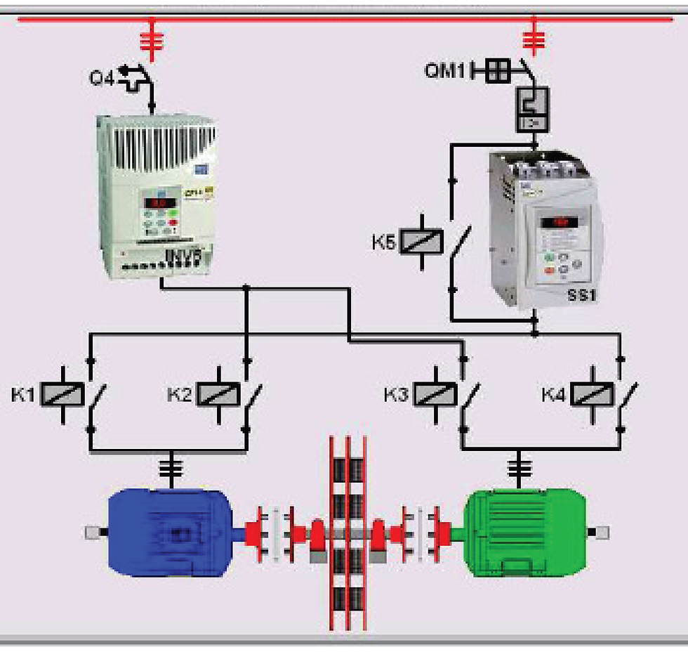
In order to achieve the minimum efficiency levels established in the regulation, the main Brazilian motor manufacturer [ ] improved its induction motor in the following ways according to a distributed folder [7]: better copper quality; fan design optimized; high performance magnetic material (USICORE); reduced airgap diameter; terminally treatment in the rotor surface; double-layer windings; and optimized slot design. These improvements were verified in the facilities of the Efficiency Energy Laboratory /UFC, which has two 10 hp three-phase induction motors (Standard and High Efficiency types) engaged to the same variable load (an electromagnetic brake), as shown in Figure 5.
Tests were performed in these motors according to the segregation loss method defined in the IEEE standard 112-1998 (E1 Method) [8] to determinate the amount of losses in each machine. The test results show the evolution of high efficiency motor, specifically the reduction of magnetic and stator losses, obtained with a volume increase of the conductive material and the use of a better quality core.
Figure 6 – shows the efficiency curve of both motors and their average efficiency is shown in Table 3. The High Efficiency motor levels measured correspond to the ones established in the Resolution.
Figure 7 – shows the test results by the type losses in both 10 CV Motors analyzed and Figure 8 shows a similar test conducted in two 150 CV Motors. In this case, the comparison is between a High-Efficiency motor and a Premium one.


Figure 8 – Losses comparison among Premium and High Efficiency 150 hp 4-pole Motor When analyzing these data we realize that the innovations to improve the efficiency differ from the increase of the machine power. In low power motor (below 50 hp), the greater concern is with the magnetic and resistive losses, while in higher powers, the mechanical losses increase its influence in the total losses and require specific treatment. The additional losses have been the object of innovation design and manufacturing processes, but the results are still to be improved.
5. Conclusions
Currently, approximately 15% of the three-phase induction motors produced in Brazil is of high efficiency level, while in the United States, the Premium motors represent 16% of the total. As noticed, the changes imposed in the levels of efficiency in Brazil, although below the international standards, have produced small scale effects. The regulation establishes that in 2010 the production of high efficiency motors should increase 100 % and the manufacturers are concerned about the achievement of this objective.
The test results showed that the improvements to achieve the high-efficiency levels took place in the increase and improve in machine’s active material. There are a lot of other improvements to be incorporated in the Brazilian manufactured process to reduce even more the losses in the induction motor. The Comparison between Standard and High Efficiency motor shows the progress achieved in the domestic industry, but the difference between national and international (Premium) levels warns to a necessity for progress in research on materials, design and manufacturing processes.


Comments